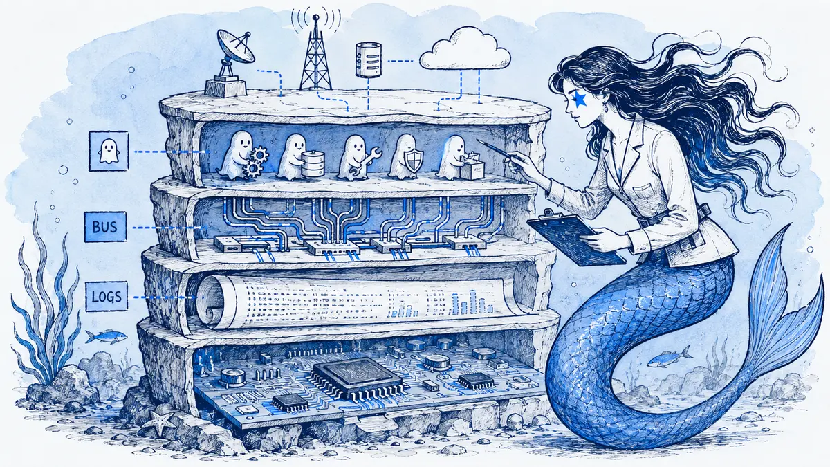
Direct answer: Document firmware architecture with a small set of linked views: a subsystem map for hardware/software boundaries, an execution-context view for interrupts, threads, ownership and hand-offs, sequence diagrams for boot/update/fault scenarios, state diagrams for operating modes, and generated tables for repetitive signals or registers. Keep timing and safety claims tied to requirements, code, measurements and tests; a diagram communicates a model, but does not prove the device behaves that way.
A firmware update, sensor timeout or watchdog reset can cross hardware, bootloader, RTOS and application boundaries. One “firmware architecture diagram” cannot show all of those at a useful level of detail. Give each view one question, state its scope and revision, and link it to the source or evidence that can verify it.
Choose the view by the review question
| View | Question it answers | Include | Verify against |
|---|---|---|---|
| System context | What is inside the device, and what external systems or operators interact with it? | Product boundary, external devices/services, key interfaces | System requirements and interface specifications |
| Subsystem or hardware/software map | Which components exist, where do they run, and how are they connected? | MCU/SoC, peripherals, bootloader, partitions, major firmware components, buses | Hardware design, build configuration and component ownership |
| Execution-context view | Which work runs in an interrupt, thread/task, work queue or DMA engine, and how is data handed off? | Context, scheduler/priority where relevant, queue or buffer, owner and synchronization boundary | RTOS configuration, source code and concurrency tests |
| Sequence diagram | In what order do participants handle one scenario, including failure and recovery? | One boot, update, shutdown, communication or fault scenario; relevant guards and timeout source | Implementation, interface contract, logs or test trace |
| State diagram | Which modes exist, and what condition moves the device between them? | States, entry/exit actions where material, guards, timeout/fault transitions and reset behavior | State-machine code, requirements and transition tests |
| Generated table | What is the full repetitive set of signals, registers, messages or configured instances? | Fields and values emitted from a named source of truth | Generator input and build/CI output |
Do not use a sequence diagram to list every subsystem, or a state diagram to explain every function call. Link a small overview to focused views when readers need to move between levels.
Show hardware boundaries and execution context separately
A subsystem map should show the device boundary, major hardware, firmware partitions or services, buses, storage, and external interfaces. Keep message-by-message behavior out of this view. Label whether a connection is a bus, interrupt, data path, control path or reset line; a bare arrow can otherwise suggest a one-way flow that the hardware does not have.
This simplified sensor path makes the interrupt-to-thread hand-off visible. Replace the components, queue rules and ownership with those in the actual system.
flowchart LR
    IMU[IMU] <-->|SPI| SENSOR[Sensor thread]
    IMU -->|interrupt| ISR[IMU ISR]
    ISR -->|signal or enqueue| QUEUE[(Sample queue)]
    QUEUE --> SENSOR
    SENSOR -->|validated sample| CONTROL[Control thread]
    CONTROL -->|output command| DRIVER[Motor driver]
    SENSOR -->|telemetry event| TQ[(Telemetry queue)]
    TQ --> COMMS[Communications thread]
The execution-context view is often where a firmware diagram becomes useful to implementers. State what the interrupt handler does and what it defers; name the queue, event or buffer at the hand-off; and identify who owns or may mutate the data. If shared memory, DMA, a ring buffer or a lock-free structure is involved, document the ownership and synchronization rule. Avoid drawing an arrow that hides a race or implies that two contexts can safely write the same state.
RTOS details are not interchangeable. For one concrete example, Zephyr documents that an ISR runs in interrupt context and recommends moving lengthy work to a thread; its thread documentation describes per-thread stacks and scheduling properties. Use the documentation for the RTOS and configuration in your project to determine which APIs are valid in an ISR, how priorities work, and what stack or memory limits apply. Do not copy Zephyr rules into a FreeRTOS, bare-metal or proprietary design without checking.
Use a sequence diagram for boot, update and fault paths
Sequence diagrams answer “what happens next?” Choose one scenario and show the normal path plus the failure branch that changes the outcome. Identify which component checks an image, switches a boot target, confirms health, records a fault or requests reset. If the ordering depends on a timeout, cite the requirement or measured/tested budget; spacing between Mermaid arrows is not timing data.
This ESP-IDF example is deliberately conditional. It assumes the project enables CONFIG_BOOTLOADER_APP_ROLLBACK_ENABLE and has a valid previous OTA application available. The running application selects the OTA partition with esp_ota_set_boot_partition() and restarts with esp_restart(); the bootloader starts the selected image in pending verification. The new application must confirm a successful self-test with esp_ota_mark_app_valid_cancel_rollback(). A failed self-test can mark the image invalid and reboot; a reset before confirmation marks it aborted, after which the bootloader selects the previous valid application. The exact states and API calls differ in other bootloaders. See the ESP-IDF OTA rollback procedure.
sequenceDiagram
    participant App as Running application
    participant OTAData as OTA data partition
    participant Device
    participant Bootloader
    participant Candidate as New application
    participant Previous as Previous valid application
    App->>OTAData: esp_ota_set_boot_partition(candidate)
    App->>Device: esp_restart()
    Device->>Bootloader: Reboot and inspect selected image
    Bootloader->>Candidate: Start candidate in pending verification
    alt Health-check result is available
        Candidate->>Candidate: Run project-defined health checks
        alt Health checks pass
            Candidate->>OTAData: Mark candidate valid
        else Health checks fail
            Candidate->>OTAData: esp_ota_mark_app_invalid_rollback_and_reboot()
            Device->>Bootloader: Restart after invalidation
            Bootloader->>Previous: Select previous valid image
        end
    else Reset before confirmation
        Device->>Bootloader: Reset with candidate still pending
        Bootloader->>Bootloader: Mark candidate aborted
        Bootloader->>Previous: Select previous valid image
    end
Treat the example as a review prompt, not a recipe to paste into firmware. Check the exact bootloader state model, update API, partition layout, anti-rollback policy, power-loss behavior and tests in the target project. If a transition is safety-relevant, link it to the requirement and the test or trace that exercises it.
The Mermaid sequence diagram syntax supports participants, alternatives and optional paths. Use those blocks to make the branch explicit. A sequence diagram shows ordering; use an oscilloscope capture, trace, timing table or other suitable artifact when the question is cycle-level timing or a physical waveform.
Model modes and recovery with a state diagram
Use a state diagram when outputs, allowed operations or safety behavior depend on the device mode. A useful review asks, for every transition: what observable event or guard triggers it, what action happens, what state follows, and how does the device recover?
stateDiagram-v2
    [*] --> Boot
    Boot --> SelfTest: startup begins
    SelfTest --> Normal: required checks pass
    SelfTest --> Safe: required check fails
    Normal --> Degraded: required input is stale or unavailable
    Degraded --> Normal: input recovers and recovery criteria pass
    Degraded --> Safe: project-defined fault guard is met
    Safe --> Boot: reset requested
The labels are placeholders for a real design. Replace “stale,” “recovery criteria” and “fault guard” with the project’s specified conditions, including units, timeout source and persistence behavior where those details matter. Do not invent a threshold to make the diagram look complete. A reset returns execution to startup; it does not establish that the underlying fault has disappeared. Mermaid’s state diagram reference documents the notation, not the correctness of the modeled behavior.
Keep timing, resources and evidence explicit
A diagram can identify a timing constraint without proving it. Distinguish among:
- Requirement: the allowed deadline or latency and where it comes from.
- Budget: the allocation among scheduling, communication, computation and I/O.
- Measurement: observed behavior from a named test, trace or target configuration.
- Illustration: an ordering or conceptual relationship with no timing guarantee.
For a hard or safety-related deadline, link the view to the relevant analysis and measured trace. Include the tested CPU/clock configuration, scheduler or interrupt assumptions when they affect the result. For resource limits, point to the configured memory, stack, queue depth, flash partition or watchdog setting rather than relying on visual box sizes.
Use separate sequence or timing views when a bus transaction, interrupt latency or response budget needs detail. Use a waveform or hardware measurement when signal shape or edge timing is the question. Mermaid is a text-based diagram syntax; it does not check schedulability, interrupt priority, data races, memory use, protocol conformance or hardware behavior.
Generate the exhaustive detail from its real source
A diagram is a poor place to enumerate every CAN signal, register bit, device-tree instance, log category or message identifier. Show the few interfaces that explain the architecture, then generate the exhaustive reference table from the project’s actual source of truth, such as a DBC, register definition, device tree, interface schema or header.
For each generated table, record the input file or generator, keep the output reproducible, and have CI detect stale generated output when the repository workflow supports it. Useful columns often include the name, unit or encoding, producer/consumer, update context, freshness or validity rule, and source definition. Include only fields that help a reader answer the question; do not make a second hand-maintained inventory that can drift from the firmware.
Make a review change traceable without calling it proof
For each view, record its scope, owner, firmware or hardware revision, and the source files or tests that support its claims. During a change review, summarize the diagram delta in concrete terms—for example, “sensor sample ownership moves from the interrupt handler to the sensor task”—then check whether code, requirements, interface documents and tests must change too. Keep the change linked to the commit, review or test result in the team’s controlled workflow.
Safety and certification evidence depends on the domain and project plan. For airborne software, the FAA’s AC 20-115D describes an acceptable means of showing compliance and recognizes DO-178C and DO-330 guidance; the FAA also says the circular is not mandatory regulation or the only means. Follow the standards, assurance plan and tool policy that apply to the product. A Mermaid rendering, Slack conversation or diagram history alone does not establish tool qualification, formal approval, requirements traceability or device behavior.
Where Arialine fits in a firmware review
When a firmware design discussion already happens in Slack, Arialine can keep a Mermaid board beside that discussion. A user can paste valid Mermaid for rendering without an AI generation call; an explicit thread request can ask for a diagram change. Applied changes are retained as versions linked to the requesting Slack message, and Branch can hold an alternate board for review.
That history records the diagram collaboration. It does not update firmware source automatically, establish that reviewers formally approved a requirement, or show that a test passed. Export the Mermaid source and connect it manually to the repository review, implementation and verification evidence. See how sequence diagrams work in Slack and reviewing diagram changes in Slack for those collaboration workflows.
Next step: choose one boot, update or fault-recovery path. Draw the participants and transitions, then attach each critical guard to the requirement, implementation and test that can verify it.
FAQ
What should a firmware architecture diagram include?
At the top level, include the product boundary, major hardware and firmware components, interfaces, and the execution or ownership boundaries needed by the reader. Use linked sequence, state or data views for detailed behavior; do not pack every signal and fault branch into one map.
Should interrupts and RTOS tasks appear in the same diagram?
They can appear in one focused execution-context view when the hand-off is the point: show the interrupt, the queue/event/buffer, the receiving task, and the relevant ownership or synchronization rule. A broader subsystem map may omit that detail.
Can a Mermaid sequence diagram prove a real-time deadline?
No. Its arrows show modeled order, not measured duration or schedulability. State the deadline and assumptions, then link to analysis, target measurements or traces. Use a timing diagram or hardware capture when signal timing itself matters.
Is Mermaid suitable for safety-critical firmware documentation?
Mermaid can communicate a design, but the renderer does not validate implementation or satisfy a project’s assurance and tool-control process by itself. Whether it can be part of a controlled artifact depends on the domain, project plan and tools policy; keep required records and evidence in the approved system.

 Add to my Slack